Technical Work: Fence Set Up
(Written January 15th, 2015)
Before our winter break, we left off our data collection discovering that the fence gave different voltage outputs depending where we chose to measure on it using the oscilloscope. We had previously assumed the voltage would be constant throughout the fence since it is a single circuit, so we were surprised to find it had varying voltages at different locations. When we measured the fence at different distances from the energizer we got different results. Unsure as to why this was happening, we wanted to be able to test multiple regions of the fence simultaneously; that way we could eliminate that other factors that were causing the variance. However, after an unfortunate accident broke part of our oscilloscope, we could only utilize one of its two channels, so we decided to order a new oscilloscope to measure and compare two spots on the fence.
In order to measure two locations at once, we needed to change our fence set up. Previously, we had been measuring the voltage output with this set up:

We measured the voltage at the energizer, at the start of the fence, and ten feet out
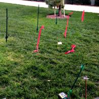
In order to compare greater distances with our oscilloscope, we changed our fence setup to look like a wave. This way we could utilize the device’s two channels to test and compare the fence at two spots simultaneously to determine if the fences voltage was changing constantly or independently and in accordance with the region we were testing. Our new fence set up looked like this:

Or in person:

Distance Measurements:

At 25ft, our voltmeter sometimes reads the same voltage (low resolution).
Written by Phillip Steiner and Adrian Maya, Technicians for High Tech High’s 2015 InvenTeam


