
Simulation
What if the limitations of time, complexity, and our busy high school schedules didn’t exist? We would quickly be able to visualize the interaction between our walker and the real world, and its various parts with each other. Hi, I’m Brianna Adewinmbi, one of the Software leads for the Rolling Robots InvenTeam who's working to make this happen!
The first step is to construct the entire walker… in a 3D simulation of course. Unity 3D is a game engine that, because of the large functionality provided by built-in libraries, makes for a great rapid prototyping tool. Our first simulated component was a LiDAR sensor because of the difficulty we had integrating it with our walker’s existing software. The simulated version consisted of a rotating red cube with a ray casted outward which informed the walker of its distance away from a wall, chair, human, or other obstacle. This is similar to how a real LiDAR sensor would use reflections from a laser to determine distance and draw an image of its surroundings.
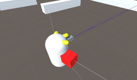
Before you ask, yes. We know this looks nothing like a walker. But the neon bright shapes protruding from the capsule are highlighted because they are each an important sensor that our walker will use to navigate. For example, the three small, yellow shapes are RF beacons, each reporting a distance from the user's watch. The gray rectangular prism is an infrared (or ultrasonic) distance sensor.
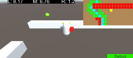
All of this comes together in our navigation algorithm pictured below. The map at the top right of the image shows obstacles detected by LiDAR in red, investigated paths in green, and the chosen path in cyan. You can see how this correlates with what the real (the simulated real, of course) world looks like with white walls preventing the walker from seeing the green watch.
See you next time, maybe with a few of these features on our walker!