November Update
(Written December 4th, 2014)
The team has been getting along fabulously. We have split into groups depending on interest and have been meeting twice a week. The meeting after school on Mondays is about two and a half hours long, while the lunch meeting on Fridays lasts for the duration of lunch. While the spark of passion is there, the bonding of family is not. It would be beneficial for the team to have a bonding day to get to know one another and hopefully improve communication in future and inevitable disagreements.
Our overall InvenTeam project objective over the course of the next eight months is to redesign the electric fence to make it more informative and efficient. We will make improvements to the notification system, as well as the overall physical design.
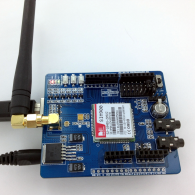
This past month, we have primarily focused on enriching our understanding of the electric fence and how it works. We began accumulating information from online research into shared documents to allow for collaboration, and bounced ideas off of each other. Knowing we wanted to improve the notification system, we also looked into understanding how SMS messages are sent, and devices such as the Arduino Uno that are capable of receiving them. After comparing a lot of potential devices, we decided on ordering the IComsat is a GSM/GPRS shield that is compatible with and will be used alongside the Arduino Uno (see figures 1 & 2). With those devices ordered, our next steps with them will be to test and make sure they are compatible with our electric fence and that we are able to access and manipulate their code.
Figure 1: IComsat GSM/GPRS shield

Figure 2: Arduino Uno

Members of our team continued to look into understanding these products and how they send/receive information so that when they do arrive, we would know where to begin. Meanwhile, the rest of our team put their research skills to the test working with an actual set up. First, we set up a small electric fence, spanning about 9 feet, and collect baseline data on its voltage output with slight variations to its set up. We found that the variables we were trying to test were insignificantly affected by the small adjustments we were making because they were returning almost identical values. To address this issue, we decided to set up and test a much larger fence. We continued searching for the best ways to accurately measure and detect breaks in the wired system, this time using two different fence energizers. The first was a lower voltage continuous stream system, and the second a high voltage 3 second pulse energizer.
Using the low voltage system, we experimented with reading our fence’s voltage directly, while with the high voltage system, we used some new equipment (a voltage divider and the accompanying adapters) to read it with an oscilloscope. The oscilloscope allowed us to read the energizer’s output more accurately, giving us the opportunity to graph its data peak to peak as well as compare each individual reading. These tools are very valuable when trying to measure the discrepancy between pulses which is key in understanding how our fence is behaving.
With the ability to accurately measure now at hand, we created data sheets and documentation systems to allow us to efficiently conduct and document our experiments. then, based on the ideas we had brainstormed, we created formats based on the different scenarios a wired fence may be interfered with and broken. Using this information, we started looking at how a break and mere interference could be distinguished, and started setting standards the actual detection system had to adhere to. Unfortunately, due to technical issues and limitations teaching group members how to use the devices we purchased, our focus was taken from the actual documentation of our work, and we did not record any specific data.
Further inquiry of the capabilities of our electric fence led us to test it under different environmental conditions. We set up a small fence and tested it with different plants and objects found in outdoor areas that our users would likely encounter themselves. We compared each condition to our regular “baseline” fence set up and noted that plants and object would affect the electrical current.
Another issue we came across, as we began working with a real electric fence, was understanding how to detect and interpret its voltage output. In order for us to make any modifications, that is, begin any coding or work with the devices we purchased; we needed to determine how our system was behaving. That way, we’d know the ranges we should be working in and targeting. Initially, we found the output was too high to be read by our voltmeter, so we fabricated our own voltage divider using standard resistors, a couple of nails, piece of wire, and plank of wood. When we went to test our creation with the fence, the current kept arching over the resistors, giving us inacurate results. After no success with a few attempted fixes, we started looking into products already on the market and decided on ordering this resistor that works with a max voltage of 2500 volts. Using this resistor it was safe enough for our group to use the oscilloscope, which allowed us to move forward. The oscilloscope can be used to give us measurable and accurate data on voltage by calculating slight differences in voltage over time. This could potentially give us the opportunity to see what variables are affecting the fence, which would provide valuable information about the areas in need of improvement.
Next Month’s Goals
Our main focus next month will be working with the Arduino Uno and IComsat is a GSM/GPRS shield. Again we will first need to understand each so we will most likely start with research. Once we have an understanding of both and how they interact, we can apply what we learned to our physical fence set up and see if we can obtain readings from the fence. Once we establish this communication and become very familiar and comfortable with it, we can work on developing our own device. Until then, we need to work on figuring out these devices, how to receive data, and determining the best way to proceed forward.
We have also met the monthly spending goal of $2500. We have spent a grand total of $2,951.92, including stipend for teachers. We plan on continuing to follow the suggested spending amounts for the coming months.
Communications
Communications has been very busy with writing a press release, creating the team logo and social media accounts, meeting with professionals in the field, as well as fundraising for the trip to Eureka Fest at M.I.T. in June.
The Communications team has developed a logo for Current Invents:
![]()
They are now preparing to send information to the press, in order to entice the media to conduct interviews with Current Invents, as well as simply spreading the word about their efforts. Current Invents has hit the ground running with its fundraising, already collecting a few hundred dollars selling laser-cut wooden turkeys with engraved personal messages, right before the Thanksgiving Break. The team has a Facebook, Twitter, Instagram, and Google Plus account. Philippe Cesson, owner and founder of the marketing and social media company Cesson 3.0, came in to help Communications with their approach and strategy. In addition to Cesson 3.0, Philippe is a professional speaker, presenting on multiple topics such as: how to grow your business, how to implement and utilize social media effectively, and how to deal with and maximize the difference in age, or generations, of your employees or clients.
Current Invents expects to finish the logo in the coming month, upload a video shot with the team’s new Go Pro Hero 4 Black Edition, and be on the news!